
Core advantage
◧
Same body, same faces
A study references the B-rep faces you selected. There is no translation step, so the load lands on the face you actually clicked.
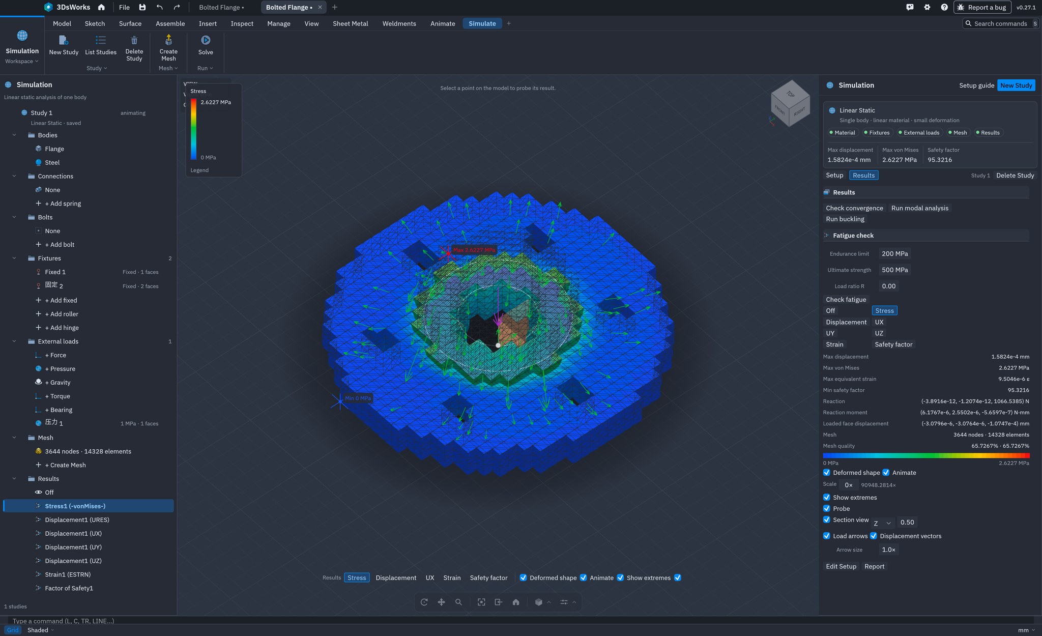
CAE runs structural studies on the same body you modelled. Pick a material, fix a face, apply a load, mesh and solve — stress, displacement and safety factor come back painted on the part, not in a separate tool with a second copy of the model.
Linear static · Modal · Buckling · Fatigue check · $0 solver seats
Export a STEP, rebuild the setup in a solver, map the results back. Every copy is a chance for the truth to drift — and a day lost before the first number appears.
A study references the B-rep faces you selected. There is no translation step, so the load lands on the face you actually clicked.
Change a fillet or a wall thickness and solve again. The study follows the geometry; nothing has to be re-imported.
The solver ships with the application. No token queue, no per-core licence, no separate simulation seat to justify.
The study is part of the file. Reopen the design on another machine and the material, fixtures, loads and mesh settings are still there.
The study tree on the left holds parts, connections, fixtures, loads, mesh and results — the same structure a dedicated FEA package uses.
Choose from 12 presets or enter Young's modulus, Poisson's ratio, yield strength and density.
Fixed, roller / slider or hinge, applied to one or more faces. Add as many as the real support needs.
Force in X / Y / Z, pressure in MPa, gravity in mm/s² or a torque in N·mm, on the faces that carry it.
Auto or fixed size, curvature-based refinement and draft quality. Node and element counts are reported before solving.
One button meshes if needed and solves the assembled system. No solver configuration file to write.
Stress, displacement, strain and safety factor, with extremes, probe, section view and an HTML report.
Grouped by the order of a study. Everything listed here ships today; nothing is a roadmap item.
Describe the physical situation: what it is made of, where it is held, what pushes on it. Read the simulation docs →
Steel, alloy steel, stainless steel, cast iron, aluminium 6061, brass, copper, magnesium, titanium, ABS, nylon and PLA, or custom properties.
Fixed, roller / slider and hinge, each a named set of faces with its own constrained directions.
Force with X / Y / Z components, pressure along the inward normal, gravity from density, or a pure torque about a vector.
Tie two faces with a spring of a given stiffness in N/mm, for mounts and interfaces that are not rigid.
A tetrahedral volume mesh built from the display surface, solved with a preconditioned conjugate-gradient solver. Read the solver notes →
Voxel cells split into four-node tetrahedra, with auto or fixed size and a reported worst / mean shape quality.
Refine where the surface curves, with minimum and maximum element size and a draft-quality option for quick runs.
Small-strain, linear-elastic solution of the assembled system, with reaction force and reaction moment reported.
Solve at three densities and compare displacement and stress. The study is converged when both changes fall within 5%.
Read the number, then find where it comes from. Every plot can be probed, sectioned and exported. Read the results docs →
von Mises stress and equivalent strain as a red-to-blue contour, with the maximum location marked on the model.
Resultant displacement and per-axis UX / UY / UZ, with an amplified deformed shape and an optional vector plot.
Yield strength divided by von Mises stress, red below 1× and blue at 3× or more, with the minimum value listed.
Click any point to read its stress, displacement, strain and safety factor, or cut the contour with a section plane.
Check the assumptions, then check the failure modes that a static contour cannot show. Read the study types →
The lowest six natural frequencies of the constrained body, with a normalized mode shape you can display.
Geometric stiffness assembled from the static stresses, returning the lowest positive load factors and their shapes.
Goodman mean-stress correction with endurance limit, ultimate strength and load ratio R, reported at the critical node.
One click writes the setup, the summary and an inline SVG stress cloud into a report you can send or archive.
A pretty stress plot on a coarse mesh is a guess with a colour scheme. The convergence check re-solves at three densities and tells you whether the answer has settled — before anyone signs off on the part.
What one run reports back, without opening a post-processor.
A short list, stated up front. If your problem is on it, use a dedicated solver — and use CAE for the design iterations that come before it.
Small strain, linear-elastic material. Large deformation, plasticity, creep and hyperelasticity are out of scope.
Heat transfer, thermal stress, CFD and electrostatics are not part of this workspace.
One primary body plus bonded bodies that touch. Interfaces can be tied with springs; sliding and frictional contact are not solved.
Impact, drop tests and crash simulation need an explicit solver. Modal and buckling are the dynamic checks available here.
Isotropic materials only. Orthotropic plies and laminate failure criteria are not modelled.
The study setup is saved with the design; the solution is recomputed. Change the geometry and the old contour is no longer valid.
Not the same tool, and not the same price. The question is how much analysis your design loop actually needs.
| Dimension | 3DsWorks CAE | Dedicated FEA |
|---|---|---|
| Licence cost | $0, free to use | Per-seat, often per solver token |
| Where the setup lives | On the CAD body, in the same file | Imported model in a separate project |
| Model transfer | None — faces are referenced directly | STEP / native import, then re-select faces |
| Study types | Static, modal, buckling, fatigue check | Static, dynamic, thermal, nonlinear, CFD, fatigue |
| Contact | Bonded bodies and springs | Frictionless, frictional, bolted, large sliding |
| Mesh control | Size, curvature, draft; tetrahedra | Hex / tet, local controls, adaptivity |
| Convergence | Three densities, 5% verdict | Manual or automated adaptivity |
| Reporting | HTML with inline SVG contour | Configurable report templates |
| Learning curve | The CAD toolbar you already use | A second application and vocabulary |
| Source code | Not published; under contract or review | Closed |
Dedicated FEA packages differ widely by edition and module. This table describes the category, not one vendor.
Download 3DsWorks, open the Simulation workspace and run a static study on a part you already know the answer for.